Abb Npcu-01 Drive Window Light Hardware for Acs800
Likewise See for ABB ACS800-01
Related Manuals for ABB ACS800-01
Summary of Contents for ABB ACS800-01
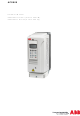
- Folio 1 ACS800 Hardware Manual ACS800-01 Drives (0.55 to 110 kW) ACS800-U1 Drives (0.75 to 150 HP)
-
Page 2: Acs800 Single Drive Manuals
ACS800 Single Drive Manuals HARDWARE MANUALS (appropriate manual is included in the delivery) ACS800-01/U1 Hardware Manual 0.55 to 110 kW (0.75 to 150 HP) 3AFE64382101 (English) ACS800-01/U1 Marine Supplement 3AFE 64291275 (English language) ACS800-02/U2 Hardware Transmission 90 to 500 kW (125 to 600 HP) - Page 3 ACS800-01 Drives 0.55 to 110 kW ACS800-U1 Drives 0.75 to 150 HP Hardware Transmission 3AFE64382101 Rev Due east EN EFFECTIVE: 15.half dozen.2004 ã 2004 ABB Oy. All Rights Reserved.
-
Page 5: Safety Instructions
To which products this chapter applies This chapter applies to the ACS800-01/U1, the ACS800-02/U2 and the ACS800-04/ Utilise of warnings and notes There are two types of safety instructions throughout this transmission: warnings and notes. -
Page vi: Installation And Maintenance Piece of work
Installation and maintenance work These warnings are intended for all who work on the bulldoze, motor cablevision or motor. Ignoring the instructions can crusade physical injury or death. Just qualified electricians are allowed to install and maintain the bulldoze. • Never work on the drive, motor cable or motor when main ability is applied. -
Page vii: Grounding
(ACS800-02: 360° high frequency grounding of cable entries is non required at the drive finish.) • Do not install a drive with EMC filter option +E202 or +E200 (available for ACS800-01 only) on an ungrounded power organization or a high resistance- grounded (over 30 ohms) ability organisation. Note: •... -
Folio viii: Fibre Optic Cables
• ACS800-01: The drive is heavy. Practice non lift it lone. Practise not lift the unit past the front end cover. Place the unit only on its back. ACS800-02, ACS800-04: The drive is heavy. Lift the bulldoze past the lifting lugs simply. -
Folio nine: Operation
Operation These warnings are intended for all who programme the functioning of the drive or operate the drive. Ignoring the instructions can cause physical injury or death or damage the equipment. Earlier adjusting the drive and putting it into service, make sure that the motor •... -
Page ten: Permanent Magnet Motor
Permanent magnet motor These are boosted warnings apropos permanent magnet motor drives. WARNING! Do not piece of work on the drive when the permanent magnet motor is rotating. Also, when the supply ability is switched off and the inverter is stopped, a rotating permanent magnet motor feeds power to the intermediate excursion of the bulldoze and the supply connections get live. -
Page 11: Table Of Contents
The ACS800-01/U1 ........ - Folio 12 Mains cable (AC line cablevision) short-circuit protection ....... .36 ACS800-01/U1, ACS800-02/U2 without enclosure extension and ACS800-04/U4 ..36 Bulldoze AC fuses (ACS800-07/U7, and ACS800-02/U2 with enclosure extension) .
- Page xiii Equipment continued to the motor cable ..........42 Installation of safety switches, contactors, connection boxes, etc.
- Page 14 RMIO board specifications ............66 Analogue inputs .
- Page xv Cooling ..............84 Degrees of protection .
- Page xvi Protection of frame sizes R2 to R5 (ACS800-01/U1) ....... . .
-
Page 17: Nigh This Manual
Technical data. The ACS800-01 is manufactured in frame sizes R2 to R6. Categorization according to the + code The instructions, technical data and dimensional drawings which business just certain optional selections are marked with + codes, e.grand. +E202. The options included in the drive can be identified from the + codes visible on the type designation characterization of the drive. -
Page 18: Contents
The ACS800-01/U1 describes the bulldoze. Mechanical installation instructs how to place and mountain the drive. -
Page 19: Installation And Commissioning Flowchart
If the converter has been non-operational for equipment are present and right. more than than i twelvemonth, the converter DC link capacitors demand to be reformed. Inquire ABB for Only intact units may be started up. instructions. If the drive is about to be connected to an Information technology... -
Page 20: Inquiries
Inquiries Address any inquiries well-nigh the production to the local ABB representative, quoting the type code and the serial number of the unit. If the local ABB representative cannot be contacted, address inquiries to the manufacturing facility. Nigh this manual... -
Page 21: The Acs800-01/U1
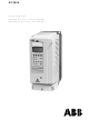
The ACS800-01/U1 What this affiliate contains This chapter describes the operating principle and construction of the drive in short. The ACS800-01/U1 The ACS800-01/U1 is a wall mountable bulldoze for controlling AC motors. Control panel CDP312R Heat sink Front cover Connection box... -
Page 22: Type Code
Type lawmaking The type code contains information on the specifications and configuration of the bulldoze. The first digits from left limited the basic configuration (eastward.g. ACS800-01- 0006-5). The optional selections are given thereafter, separated by + signs (e.grand. +E202). The main selections are described below. Not all selections are bachelor for all types. -
Folio 23: Principal Circuit And Control
Air conditioning voltage to DC voltage capacitor banking concern energy storage which stabilizes the intermediate circuit DC voltage half-dozen-pulse IGBT inverter converts the DC voltage to AC voltage and vice versa. The motor operation is controlled by switching the IGBTs. The ACS800-01/U1... -
Folio 24: Printed Circuit Boards
Motor control The motor control is based on the Direct Torque Control (DTC) method. Two stage currents and DC link voltage are measured and used for the control. The third stage electric current is measured for globe error protection. The ACS800-01/U1... -
Folio 25: Mechanical Installation
Mechanical installation Unpacking the unit of measurement The bulldoze is delivered in a box that also contains: • plastic pocketbook containing: screws (M3), clamps and cable lugs (two mm , M3) for grounding the command cable screens • connection box (screws, clamps and vibration dampers with +C131 included) •... -
Page 26: Commitment Check
Delivery bank check Check that there are no signs of impairment. Earlier attempting installation and operation, check the information on the type designation label of the drive to verify that the unit is of the correct type. The label includes an IEC and NEMA rating, UL, C-UL, CSA and CE markings, a type lawmaking and a series number, which allow individual recognition of each unit. -
Page 27: Gratis Space Effectually The Unit of measurement
Gratis space effectually the unit Required gratis space effectually the drive to enable cooling air flow, service and maintenance is shown below in millimetres and [inches]. When mounting IP 55 units above one another, exit 200 mm (7.ix in.) free space above and beneath the unit. 50 [two.0] 200 [7.9] fifty [2.0]... -
Folio 28: Mounting The Drive On The Wall
IP 55 (UL type 12) marine applications (+C132) of frame sizes R4 to R6 See ACS800-01/U1 Marine Supplement [3AFE68291275 (English)]. Units with vibration dampers (+C131) See ACS800-01/U1 Vibration Damper Installation Guide [3AFE68295351 (English language)]. UL 12 units Install the hood delivered with the drive 50 mm (2.0 in.) higher up the tiptop of unit. -
Page 29: Cabinet Installation
Cabinet installation The required distance between parallel units is five millimetres (0.2 in.) in installations without the front cover. The cooling air entering the unit must not exceed +40 °C ( +104 °F) . Preventing cooling air recirculation Prevent air recirculation inside and outside the cabinet. Case AREA Primary air menstruum out... -
Page thirty: Unit Above Another
Unit of measurement above another Lead the out-coming cooling air away from the unit above. Case max.+40 °C (+104 °F) Mechanical installation... -
Folio 31: Planning The Electrical Installation
Always follow local regulations. Annotation: If the recommendations given by ABB are not followed, the drive may feel bug that the warranty does not cover. To which products this affiliate applies... -
Folio 32: Protecting The Motor Insulation And Bearings
The stress on motor insulation can be avoided by using optional ABB du/dt filters. du/dt filters also reduce bearing currents. -
Page 33: Requirements Table
Requirements table The following table shows how to select the motor insulation system and when an optional ABB du/dt filter, insulated North-cease (non-driven end) motor bearings and ABB mutual fashion filters are required. The motor manufacturer should exist consulted regarding the construction of the motor insulation and boosted requirements for explosion-prophylactic (EX) motors. - Folio 34 For motors with higher rated output than what is stated for the detail frame size in EN 50347 (2001) and for IP 23 motors, the requirements of ABB random-wound motor series M3AA, M3AP, M3BP are given below. For other motor types, meet the Requirements table above.
-
Page 35: Permanent Magnet Synchronous Motor
Supply connection Disconnecting device (disconnecting means) ACS800-01, ACS800-U1, ACS800-02, ACS800-U2 without enclosure extension, ACS800-04, ACS800-U4 Install a paw-operated input disconnecting device (disconnecting means) betwixt the AC ability source and the bulldoze. The disconnecting device must be of a type that tin be locked to the open position for installation and maintenance work. -
Page 36: Thermal Overload And Short-Circuit Protection
(see Technical Information). ACS800-01/U1, ACS800-02/U2 without enclosure extension and ACS800-04/U4 When placed at the distribution board, standard gG (US: CC or T for the ACS800- U1; T or Fifty for the ACS800-U2 and ACS800-U4) fuses will protect the input cable in short-circuit situations, restrict bulldoze damage and prevent damage to bordering equipment in instance of a short-circuit inside the bulldoze. -
Page 37: Circuit Breakers
Circuit breakers Circuit breakers which accept been tested by ABB with the ACS800 tin can be used. Fuses must be used with other circuit breakers. Contact your local ABB representative for approved breaker types and supply network characteristics. The protective characteristics of circuit breakers depend on the blazon, construction and settings of the breakers. -
Page 38: Prevention Of Unexpected Start
Prevention of Unexpected Start The drive can exist equipped with an optional Prevention of Unexpected Start office co-ordinate to standards IEC/EN 60204-ane: 1997; ISO/DIS 14118: 2000 and EN 1037: 1996. The Prevention of Unexpected Start office disables the control voltage of the ability semiconductors, thus preventing the inverter from generating the Air-conditioning voltage required to rotate the motor. -
Page 39: Selecting The Power Cables
Selecting the power cables General rules Dimension the mains (input ability) and motor cables co-ordinate to local regulations: • The cablevision must be able to bear the bulldoze load current. See chapter Technical data for the rated currents. ° • The cable must be rated for at least lxx C maximum permissible temperature of conductor in continuous use. -
Page twoscore: Culling Ability Cable Types
Alternative ability cable types Power cable types that tin can be used with the drive are represented below. Recommended Symmetrical shielded cable: three phase conductors A separate PE conductor is required if the conductivity and a concentric or otherwise symmetrically of the cable shield is < 50 % of the electrical conductivity of the constructed PE conductor, and a shield phase conductor. -
Page 41: Additional Us Requirements
Additional Usa requirements Blazon MC continuous corrugated aluminum armor cablevision with symmetrical grounds or shielded power cablevision must be used for the motor cables if metallic conduit is not used. For the North American market, 600 VAC cablevision is accepted for up to 500 VAC. 1000 VAC cable is required above 500 VAC (below 600 VAC). -
Folio 42: Equipment Connected To The Motor Cable
Equipment continued to the motor cablevision Installation of safety switches, contactors, connectedness boxes, etc. To minimize the emission level when safety switches, contactors, connexion boxes or like equipment are installed in the motor cable (i.e. between the drive and the motor): •... -
Folio 43: Protecting The Relay Output Contacts And Attenuating Disturbances In Case Of Inductive Loads
Protecting the relay output contacts and attenuating disturbances in case of inductive loads Anterior loads (relays, contactors, motors) crusade voltage transients when switched off. The relay contacts on the RMIO lath are protected with varistors (250 V) against overvoltage peaks. In spite of this, it is highly recommended to equip inductive loads with noise attenuating circuits [varistors, RC filters (Ac) or diodes (DC)] in order to minimize the EMC emission at switch-off. -
Page 44: Selecting The Control Cables
Control panel cablevision In remote utilize, the cable connecting the control panel to the bulldoze must non exceed 3 metres (10 ft). The cable type tested and approved by ABB is used in control panel pick kits. Planning the electrical installation... -
Page 45: Connexion Of A Motor Temperature Sensor To The Drive I/O
Connectedness of a motor temperature sensor to the drive I/O WARNING! IEC 60664 requires double or reinforced insulation between alive parts and the surface of accessible parts of electric equipment which are either non- conductive or conductive but not continued to the protective world. To fulfil this requirement, the connexion of a thermistor (and other similar components) to the digital inputs of the bulldoze tin can be implemented in three alternating ways:... -
Page 46: Control Cable Ducts
A diagram of the cablevision routing is shown beneath. Motor cable Drive min 300 mm (12 in.) Power cable Input power cable Motor cable 90 ° min 200 mm (8 in.) min 500 mm (twenty in.) Control cables Control cable ducts 24 5 230 V 24 5 230 5... -
Page 47: Electrical Installation
Electrical installation What this chapter contains This chapter describes the electrical installation procedure of the drive. Warning! The work described in this chapter may but be carried out past a qualified electrician. Follow the Condom instructions on the first pages of this transmission. Ignoring the safety instructions tin crusade injury or death. -
Page 48: Checking The Insulation Of The Assembly
Disconnect the EMC filter capacitors of selections +E202 and +E200 earlier connecting the drive to an ungrounded organization. For detailed instructions on how to do this, please contact your local ABB distributor. Alert! If a bulldoze with EMC filter selection +E202 or +E200 is installed on an It... -
Page 49: Connecting The Power Cables
Connecting the power cables Diagram Drive OUTPUT INPUT UDC+ V1 W1 U2 V2 W2 (PE) (PE) Optional brake For alternatives, see resistor Planning the electric Motor installation: Disconnecting device (disconnecting means) 1), 2) Grounding of the motor cable shield at the motor finish If shielded cablevision is used (not required but For minimum radio frequency interference: recommended), use a separate PE cable (ane) or a... -
Page 50: Conductor Stripping Lengths
Conductor stripping lengths Strip the usher ends as follows to fit them within the power cable connection terminals. Frame size Stripping length R2, R3 0.39 R4, R5 0.63 ane.10 Allowed wire sizes, tightening torques Technical information: Cable entries. Wall installed units (European version) Power cablevision installation process 1. - Folio 51 Connection box (IP 21) Fastening hooks Dorsum plate Fastening screws 360 degrees grounding clamp Grommet Motor cable entry Input cable entry Restriction resistor cablevision entry Command cable entry Bottom plate Fasten the control cables betwixt these plates with cable Encompass ties Frame sizes R2 to R4 UDC+...
- Page 52 Frame size R5 UDC+ UDC- Electrical installation...
- Folio 53 Frame size R6: Cable lug installation [xvi to 70 mm (6 to two/0 AWG) cables] Connection plate Isolate the ends of fastening screws the cable lugs with insulating tape or compress tubing. Frame size R6: Cable final installation [95 to 185 mm (3/0 to 350 AWG)] cables a.
-
Page 54: Wall Installed Units (U.s.a. Version)
Wall installed units (Us version) 1. Remove the front cover (in frame size R6 the lower forepart cover) by releasing the retaining clip with a screw driver and lifting the cover from the lesser outwards. 2. Make the cablevision entry holes in the gland box by breaking off the suitable knock-out plates with a screw driver. -
Folio 55: Warning Sticker
Wire size Pinch lug Crimping tool kcmil/AWG Manufacturer Type Manufacturer Type No. of crimps Burndy YAV6C-L2 Burndy MY29-three Ilsco CCL-6-38 Ilsco ILC-ten Burndy YA4C-L4BOX Burndy MY29-iii Ilsco CCL-four-38 Ilsco MT-25 Burndy YA2C-L4BOX Burndy MY29-3 Ilsco CRC-2 Ilsco IDT-12 Ilsco CCL-2-38 Ilsco MT-25 Burndy... -
Page 56: Frame Size R5
Protect the RMIO board terminals X25 to X27 confronting contact when input voltage exceeds 50 VAC. Frame size R5 Embrace the power cable terminals as follows: i. Cut holes for the installed cables into the clear plastic shroud. 2. Printing the shroud onto the terminals. Removal of the shroud with a spiral driver: Electrical installation... -
Page 57: Frame Size R6
Frame size R6 Cover the power cable terminals as follows: 1. Cut holes for the installed cables into the clear plastic shroud in cable lug installations. 2. Press the shroud onto the terminals. View of cable final installation Removal of the shroud by lifting upward with a spiral commuter from the corner: Electrical installation... -
Page 58: Connecting The Control Cables
Connecting the control cables Atomic number 82 the cable through the control cablevision entry (1). Connect the control cables as described below. Connect the conductors to the appropriate detachable terminals of the RMIO board [refer to chapter Motor command and I/O board (RMIO)]. - Folio 59 Frame sizes R5 and R6 View of frame size R6 Control panel Optional module two Optional module 1 DDCS advice pick module 3: RDCO Place the warning sticker here Command cable Detachable connexion terminals (pull up) grounding: come across section degrees grounding Electric installation...
-
Page sixty: Degrees Grounding
360 degrees grounding Insulation Double-shielded cable Single-shielded cablevision When the outer surface of the shield is covered with non-conductive cloth • Strip the cable carefully (do not cutting the grounding wire and the shield) • Turn the shield inside out to betrayal the conductive surface. •... -
Folio 61: Cabling Of I/O And Fieldbus Modules
Cabling of I/O and fieldbus modules Module As short as possible Shield Notation: The RDIO module does not include a terminal for cable shield grounding. Ground the pair cable shields here. Pulse encoder module cabling As brusk as possible Note1: If the encoder is of unisolated type, ground the encoder cablevision at the drive cease simply. -
Page 62: Fastening The Control Cables And Covers
Fastening the control cables and covers When all control cables are connected, fasten them together with cable ties. Units with a connection box: spike the cables to the entry plate with cable ties. Units with a gland box: tighten the clamping nuts of the cablevision glands. Fasten the connection box embrace. -
Page 63: Motor Control And I/O Board (Rmio)
Motor control and I/O lath (RMIO) What this chapter contains This chapter shows • external control connections to the RMIO board for the ACS800 Standard Awarding Program (Mill Macro) • specifications of the inputs and outputs of the board. To which products this chapter applies This affiliate applies to ACS800 units which utilise the RMIO board. -
Page 64: External Control Connections (Not-Us)
External control connections (not-US) External control cablevision connections to the RMIO board for the ACS800 Standard Awarding Programme (Factory Macro) are shown beneath. For external control connections of other awarding macros and programs, see the advisable Firmware Transmission. RMIO RMIO VREF- Reference voltage -x VDC, 1 kohm <... -
Folio 65: External Control Connections (Us)
External command connections (U.s.) External control cable connections to the RMIO board for the ACS800 Standard Awarding Program (Mill Macro US version) are shown below. For external control connections of other application macros and programs, see the appropriate Firmware Manual. RMIO RMIO VREF-... -
Page 66: Rmio Board Specifications
RMIO board specifications Analogue inputs With Standard Application Programme two programmable differential current inputs (0 mA / 4 mA ... 20 mA, R = 100 ohm) and one programmable differential voltage input (-10 V / 0 V / ii V ... +10 V, R >... -
Page 67: Relay Outputs
Maximum continuous electric current ii A rms Isolation exam voltage four kVAC, one minute DDCS fibre optic link With optional communication adapter module RDCO. Protocol: DDCS (ABB Distributed Drives Communication Organisation) 24 VDC power input Voltage 24 VDC ± 10 %... - Page 68 Isolation and grounding diagram (Test voltage: 500 V Air-conditioning) VREF- AGND VREF+ AGND AI1+ Common mode AI1- voltage between AI2+ channels ±fifteen Five AI2- AI3+ AI3- AO1+ AO1- AO2+ AO2- Jumper J1 settings: DGND1 All digital inputs share a common ground.
-
Page 69: Installation Checklist
Installation checklist Checklist Cheque the mechanical and electrical installation of the bulldoze before offset-upwards. Become through the checklist beneath together with another person. Read the Safety instructions on the first pages of this manual earlier you piece of work on the unit. Bank check MECHANICAL INSTALLATION The ambient operating conditions are allowed. - Folio 70 Installation checklist...
-
Page 71: Maintenance
Ignoring the prophylactic instructions can cause injury or decease. Maintenance intervals If installed in an appropriate environment, the drive requires very fiddling maintenance. This tabular array lists the routine maintenance intervals recommended by ABB. Maintenance Interval Education... -
Page 72: Heatsink
If the bulldoze is operated in a critical part of a process, fan replacement is recommended once these symptoms beginning appearing. Replacement fans are available from ABB. Do not use other than ABB specified spare parts. -
Page 73: Fan Replacement (R4)
Fan replacement (R4) ane. Loosen the screws that fasten the fan mounting plate to the frame. 2. Push the fan mounting plate to the left and pull it out. 3. Disconnect the fan power cable. 4. Undo the screws that fasten the fan to the fan mounting plate. 5. -
Page 74: Fan Replacement (R5)
Fan replacement (R5) ane. Undo the fastening screws of the swing-out frame. 2. Open the swing-out frame. 3. Disconnect the cable. 4. Undo the fastening screws of the fan. 5. Install the new fan in reverse order. Lesser view Maintenance... -
Page 75: Fan Replacement (R6)
Fan replacement (R6) To remove the fan, undo the fixing screws. Disconnect the cable. Install the new fan in reverse order. Bottom view Additional fan There is an additional cooling fan in all IP 55 units and most IP 21 units. Still, there is no additional fan in the following IP 21 units: -0050-two to -0070-2, -0003-3 to - 0005-3, -0070-3 to -0120-3, -0004-5 to -0006-5, -0100-5 to -0140-5. -
Page 76: Replacement (R6)
It is not possible to predict a capacitor failure. Capacitor failure is usually followed by a mains fuse failure or a mistake trip. Contact ABB if capacitor failure is suspected. Replacements for frame size R4 and up are available from ABB. Do not use other than ABB specified spare parts. -
Page 77: Technical Data
CE and other markings and warranty policy. IEC ratings The IEC ratings for the ACS800-01 with 50 Hz and 60 Hz supplies are given below. The symbols are described below the tabular array. ACS800-01 size... -
Page 78: Symbols
ACS800-01 size Nominal Low-cal-overload Heavy-duty utilise Frame Air flow Estrus overload ratings size dissipation cont.max cont.max 3-phase supply voltage 380 V, 400 V, 415 V, 440 V, 460 V, 480 Five or 500 V -0004-five -0005-5 -0006-5 10.8 -0009-5 10.5 thirteen.8... -
Folio 79: Sizing
In altitudes from chiliad to 4000 m (3300 to 13123 ft) in a higher place sea level, the derating is 1 % for every 100 m (328 ft). For a more than authentic derating, use the DriveSize PC tool. If the installation site is higher than 2000 m (6600 ft) to a higher place body of water level, please contact your local ABB distributor or office for farther information. -
Folio 80: Mains Cable Fuses
Note 1: In multicable installations, install only one fuse per stage (not one fuse per conductor). Notation ii: Larger fuses must non exist used. Note iii: Fuses from other manufacturers tin exist used if they come across the ratings. ACS800-01 size Input Fuse... - Page 81 ACS800-01 size Input Fuse current Manufacturer Type IEC size Three-stage supply voltage 380 V, 400 V, 415 Five, 440 Five, 460 V, 480 V or 500 V -0004-five ABB Control OFAF000H10 -0005-5 ABB Control OFAF000H10 -0006-5 ABB Control OFAF000H10 -0009-5 10.0...
-
Page 82: Cable Types
Cablevision types The table below gives copper and aluminium cable types for different load currents. Cable sizing is based on max. 9 cables laid on a cable ladder next, ambient temperature xxx °C, PVC insulation, surface temperature 70 °C (EN 60204-ane and IEC 60364-five-2/2001). -
Page 83: Dimensions, Weights And Noise
Dimensions, weights and noise H1 height with cable connectedness box, H2 height without cable connection box. Frame IP 21 IP 55 Noise size Width Depth Weight Summit Width Depth Weight Input power connexion Voltage (U 208/220/230/240 VAC 3-phase ± 10 % for 230 VAC units 380/400/415 VAC 3-phase ±... -
Page 84: Efficiency
Maximum recommended Sizing method Max. motor cable length motor cable length DTC control Scalar command according to I and I R2 to R3: 100 g (328 ft) R2: 150 chiliad (492 ft) according to I R4 to R6: 300 m (984 ft) R3 to R6: 300 m (984 ft) cont.max ambient temperatures below... -
Page 85: Ambient Conditions
Ambient conditions Environmental limits for the bulldoze are given below. The drive is to be used in a heated, indoor, controlled environment. Functioning Storage Transportation installed for stationary employ in the protective parcel in the protective package Installation site altitude 0 to 4000 g (13123 ft) above bounding main level [above thou m (3281 ft), see section... -
Page 86: Materials
European union. They must be removed and handled co-ordinate to local regulations. For further information on environmental aspects and more detailed recycling instructions, please contact your local ABB benefactor. Applicable standards The drive complies with the post-obit standards. The compliance with the European Low Voltage Directive is verified co-ordinate to standards EN 50178 and EN 60204-i. -
Page 87: Ce Marker
CE marking A CE mark is attached to the drive to verify that the unit of measurement follows the provisions of the European Low Voltage and EMC Directives (Directive 73/23/EEC, as amended by 93/68/EEC and Directive 89/336/ EEC, as amended past 93/68/EEC). Definitions EMC stands for Electromagnetic Compatibility. -
Page 88: Second Environment
Equipment ii. An EMC programme for preventing disturbances is fatigued up for the installation. A template is available from the local ABB representative. iii. The motor and control cables are selected as specified in the Hardware Manual. iv. The drive is installed according to the instructions given in the Hardware Manual. -
Page 89: C-Tick" Marking
"C-tick" marking A "C-tick" marker is fastened to each drive in lodge to verify compliance with the relevant standard (IEC 61800-3 (1996) – Adjustable speed electrical power drive systems – Part 3: EMC product standard including specific test methods), mandated by the Trans-Tasman Electromagnetic Compatibility Scheme. -
Page 90: 2d Surround
In no event shall the manufacturer, its suppliers or subcontractors be liable for special, indirect, incidental or consequential damages, losses or penalties. If you accept any questions concerning your ABB drive, please contact the local distributor or ABB office. The technical data, information and specifications are valid at the time of printing. The manufacturer reserves the correct to modifications without prior notice. -
Folio 91: U.s.a. Tables
Us tables NEMA ratings The NEMA ratings for the ACS800-U1 with 60 Hz supplies are given below. The symbols are described below the tabular array. For sizing, derating and 50 Hz supplies, encounter ratings. ACS800-U1 size Normal use Heavy-duty use Frame Air flow Heat size... -
Page 92: Symbols
Overload may be express to v % at high speeds (> xc % speed) by the internal power limit of the bulldoze. The limitation too depends on motor characteristics and network voltage. Overload may be express to forty % at high speeds (> xc % speed) by the internal power limit of the drive. - Page 93 ACS800-U1 blazon Input Fuse current Manufacturer Type UL course Three-phase supply voltage 208 Five, 220 Five, 230 5 or 240 V -0002-2 Bussmann JJS-ten -0003-two Bussmann JJS-10 -0004-2 Bussmann JJS-15 -0006-2 Bussmann JJS-25 -0009-2 Bussmann JJS-30 -0011-two Bussmann JJS-xl -0016-2 Bussmann JJS-50 -0020-two...
-
Page 94: Cable Types
Cablevision types Cable sizing is based on NEC Table 310-16 for copper wires, 75 °C (167 °F) wire insulation at forty °C (104 °F) ambient temperature. Not more than three current-carrying conductors in raceway or cable or earth (direct cached). For other conditions, dimension the cables co-ordinate to local rubber regulations, appropriate input voltage and the load current of the drive. -
Page 95: Dimensions And Weights
sixteen.54 UL/CSA markings The ACS800-01 and ACS800-U1 units of UL type 1 are C-UL Usa listed and CSA marked. The UL and CSA markings are pending for units of UL type 12. The drive is suitable for use on a circuit capable of delivering non more 65 kA rms symmetrical amperes at the bulldoze nominal voltage (600 V maximum for 690 5 units). - Page 96 Technical data...
-
Page 97: Dimensional Drawings
Dimensional drawings Dimensional drawings of the ACS800-01 are shown below. The dimensions are given in milllimetres and [inches]. Dimensional drawings... -
Page 98: Frame Size R2 (Ip 21, Ul Type one)
Frame size R2 (IP 21, UL type ane) Dimensional drawings... -
Folio 99: Frame Size R2 (Ip 55, Ul Blazon 12)
Frame size R2 (IP 55, UL type 12) Dimensional drawings... -
Page 100: Frame Size R3 (Ip 21, Ul Type 1)
Frame size R3 (IP 21, UL type 1) Dimensional drawings... -
Folio 101: Frame Size R3 (Ip 55, Ul Type 12)
Frame size R3 (IP 55, UL blazon 12) Dimensional drawings... -
Page 102: Frame Size R4 (Ip 21, Ul Type 1)
Frame size R4 (IP 21, UL type one) Dimensional drawings... -
Page 103: Frame Size R4 (Ip 55, Ul Type 12)
Frame size R4 (IP 55, UL type 12) Dimensional drawings... -
Page 104: Frame Size R5 (Ip 21, Ul Type 1)
Frame size R5 (IP 21, UL blazon 1) Dimensional drawings... -
Page 105: Frame Size R5 (Ip 55, Ul Blazon 12)
Frame size R5 (IP 55, UL type 12) Dimensional drawings... -
Page 106: Frame Size R6 (Ip 21, Ul Blazon 1)
Frame size R6 (IP 21, UL type ane) Dimensional drawings... -
Page 107: Frame Size R6 (Ip 55, Ul Type 12)
Frame size R6 (IP 55, UL type 12) Dimensional drawings... -
Page 108: Dimensional Drawings (U.s.)
Dimensional drawings (U.s.) Dimensional drawings of the ACS800-U1 are shown below. The dimensions are given in milllimetres and [inches]. Dimensional drawings... -
Folio 109: Frame Size R2 (Ul Type 1, Ip 21)
Frame size R2 (UL blazon 1, IP 21) Dimensional drawings... -
Page 110: Frame Size R2 (Ul Type 12, Ip 54)
Frame size R2 (UL type 12, IP 55) Dimensional drawings... -
Page 111: Frame Size R3 (Ul Type 1, Ip 21)
Frame size R3 (UL type 1, IP 21) Dimensional drawings... -
Page 112: Frame Size R3 (Ul Type 12, Ip 54)
Frame size R3 (UL blazon 12, IP 55) Dimensional drawings... -
Page 113: Frame Size R4 (Ul Type 1, Ip 21)
Frame size R4 (UL type 1, IP 21) Dimensional drawings... -
Page 114: Frame Size R4 (Ul Type 12, Ip 54)
Frame size R4 (UL blazon 12, IP 55) Dimensional drawings... -
Page 115: Frame Size R5 (Ul Type 1, Ip 21)
Frame size R5 (UL type 1, IP 21) Dimensional drawings... -
Page 116: Frame Size R5 (Ul Blazon 12, Ip 54)
Frame size R5 (UL type 12, IP 55) Dimensional drawings... -
Folio 117: Frame Size R6 (Ul Type one, Ip 21)
Frame size R6 (UL blazon 1, IP 21) Dimensional drawings... -
Page 118: Frame Size R6 (Ul Type 12, Ip 54)
Frame size R6 (UL type 12, IP 55) Dimensional drawings... -
Page 119: Resistor Braking
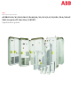
The chapter also contains the technical data. To which products this chapter applies This chapter applies to the ACS800-01/U1 (frame sizes R2 to R6), ACS800-02/U2 (frame sizes R7 and R8), ACS800-04/U4 (frame sizes R7 and R8) and ACS800-07/ U7 (frame sizes R6, R7 and R8). -
Page 120: Optional Brake Chopper And Resistor(S) For The Acs800-01/U1
) is sufficient for the application (run into step three above). Optional brake chopper and resistor(south) for the ACS800-01/U1 The nominal ratings for dimensiong the brake resistors for the ACS800-01 and ACS800-U1 are given below at an ambience temperature of 40 °C (104 °F). ACS 800-01 blazon... - Folio 121 ACS 800-01 type Braking power of Brake resistor(s) ACS 800-U1 type the chopper and the drive Type brcont Rcont (kW) (ohm) (kJ) (kW) 400 V units -0003-3 SACE08RE44 -0004-3 SACE08RE44 -0005-iii SACE08RE44 -0006-3 SACE08RE44 -0009-3 SACE08RE44 -0011-3 SACE15RE22 -0016-three SACE15RE22 -0020-3 SACE15RE22 -0025-iii...
-
Page 122: Acs800-07/U7
Optional restriction chopper and resistor(south) for the ACS800-02/U2, ACS800-04/ 04M/U4 and ACS800-07/U7 The nominal ratings for dimensiong the brake resistors for the ACS800-02/U2, ACS800-04/04M/U4 and ACS800-07/U7 are given below at an ambient temperature of twoscore °C (104 °F). ACS 800 type Frame Braking ability of the chopper and the Brake resistor(s) - Page 123 ACS 800 type Frame Braking power of the chopper and the Brake resistor(s) size drive five/sixty due south 10/60 s 30/threescore south Type Rcont (ohm) (kJ) (kW) br10 br30 brcont (kW) (kW) (kW) (kW) 690 V units -0070-vii SAFUR90F575 eight.00 1800 -0100-7 SAFUR80F500 6.00...
-
Folio 124: Resistor Installation And Wiring
Combined braking cycles for R7: Examples max 5 s or 10 s or P br10 br30 brcont No braking max 30 southward min. 30 southward min. 30 s max 30 southward min. 30 s • After P or P braking, the drive and the chopper will withstand P continuously. -
Page 125: Acs800-07/U7
Note: If an external brake chopper (exterior the drive module) is used, a chief contactor is always required. A thermal switch (standard in ABB resistors) is required for safety reasons. The cablevision must be shielded and not longer than the resistor cable. -
Page 126: Restriction Circuit Commissioning
OFF2 Stop. For the use of the brake resistor overload protection (parameters 27.02...27.05), consult an ABB representative. WARNING! If the drive is equipped with a restriction chopper just the chopper is not enabled by parameter setting, the brake resistor must be disconnected because the protection against resistor overheating is then non in apply. -
Page 127: External +24 Five Ability Supply For The Rmio Board
External +24 Five power supply for the RMIO board What this chapter contains This chapter describes how to connect external +24 V power supply for the RMIO board. When to utilise External +24 5 power supply for the RMIO lath is recommended if •... -
Page 128: Connecting +24 5 External Power Supply
Connecting +24 V external power supply 1. Break off the tab roofing the +24 VDC power input connector with pliers. 2. Lift the connector upwards. 3. Disconnect the wires from the connector (continue the connector for later apply). 4. Isolate the ends of the wires individually with insulating tape. 5. - Page 129 External +24 5 power supply for the RMIO lath...
- Folio 130 External +24 V power supply for the RMIO board...
- Folio 132 ABB Oy ABB Inc. AC Drives Automation Technologies P.O. Box 184 Drives & Motors FI-00381 HELSINKI 16250 West Glendale Bulldoze FINLAND New Berlin, WI 53151 Telephone +358 ten 22 11 +358 x 22 22681 Telephone 262 785-3200 Net http://www.abb.com 800-HELP-365...
0 Response to "Abb Npcu-01 Drive Window Light Hardware for Acs800"
Post a Comment